Starter Kits,Controller Board, Sensor Modules Factory
DIY Educational programmable Robot Projects manufacturer
 |
| Place of Origin: | Guangdong China (Mainland) |
| Brand Name: | Oky Newstar |
| Model Number: | oky4008 |
| Minimum Order Quantity: | 10 Piece/Pieces |
|---|---|
| Price: | USD2.38-2.8/piece |
| Packaging Details: | Different package at optional: 1. Retailing Package:Anti-static bag 2. Bulking Packing:Plastic Bag Package 3. Retailing Box package design according to your requirement( Order > 3000PCS) |
| Delivery Time: | 3-5 workdays after payment |
| Payment Terms: | L/C,D/A,D/P,T/T,Western Union,MoneyGram |
| Supply Ability: | 1000 Piece/Pieces per Day |
| Type: | 2004A | Matrix Number: | 20*4 |
|---|---|---|---|
| Working Voltage: | 5V | LCD Type & Color: | STN(Blue)- FSTN |
| Working Temp: | :-20~70℃ | View Angle: | 6 O'clock |
| Highlight: | shields for arduino,arduino temperature sensor |
||
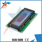
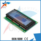
5V 2004 20X4 204 2004A LCD Display Module Blue Screen
Quick Detail:
| Working Voltage | 5V |
| LCD type & color | STN(Blue)- FSTN |
| Working Temp | :-20~70℃ |
| View angle | 6 O'clock |
| Display type | positive / negative type |
| Control IC & package | KS0073 or EQV- COB |
| Character size(W x H) | 2.94 x 4.74mm |
| Viewing area(W x H) | 76.0 x 26.0mm |
| Dot Size | 0.54*0.54mm |
| Weight | 74g |
Description:
The latest IIC LCD2004-character LCD display module, a new high quality 4 line 20 character LCD module not only set the contrast control knob selector switch also has a backlight and IIC communication interface. For Arduino beginners, not for the cumbersome and complex LCD driver circuit connection and a headache, the real significance of this LCD module will simplify the circuit, this module directly into the Arduino Sensor Shield V5.0 sensor expansion board IIC device interface can, GM 4P sensor connection cable, programmed through the Arduino controller, you can easily identify the slogan, sensor data records.
Specifications:
Use your solderless breadboard and wire jumpers to make these connections:
*Use a breadboard rail to make multiple connections to the Arduino GND pin
*For potentiometer connection, use the potentiometer's center pin and either of the other pins to make the connection from LCD pin 3 to Arduino GND
** A current limiting resistor or potentiometer (40 Ohm minimum) should be used to avoid excessive current. It should look something like this:
Software
Here is the driver code:/* ------------------------------------------------------------------------------- */
// character LCD example code
// www.hacktronics.com
#include <LiquidCrystal.h>
// Connections:
// rs (LCD pin 4) to Arduino pin 12
// rw (LCD pin 5) to Arduino pin 11
// enable (LCD pin 6) to Arduino pin 10
// LCD pin 15 to Arduino pin 13
// LCD pins d4, d5, d6, d7 to Arduino pins 5, 4, 3, 2
LiquidCrystal lcd(12, 11, 10, 5, 4, 3, 2);
int backLight = 13; // pin 13 will control the backlight
void setup()
{
pinMode(backLight, OUTPUT);
digitalWrite(backLight, HIGH); // turn backlight on. Replace 'HIGH' with 'LOW' to turn it off.
lcd.begin(20,4); // columns, rows. use 16,2 for a 16x2 LCD, etc.
lcd.clear(); // start with a blank screen
lcd.setCursor(0,0); // set cursor to column 0, row 0 (the first row)
lcd.print("Hello, World"); // change this text to whatever you like. keep it clean.
lcd.setCursor(0,1); // set cursor to column 0, row 1
lcd.print("keyes");
// if you have a 4 row LCD, uncomment these lines to write to the bottom rows
// and change the lcd.begin() statement above.
//lcd.setCursor(0,2); // set cursor to column 0, row 2
//lcd.print("Row 3");
//lcd.setCursor(0,3); // set cursor to column 0, row 3
//lcd.print("Row 4");
}
void loop()
{
}
/* ------------------------------------------------------------------------------- */
You will now have a folder called ?LCD_example?
Start the Arduino software and load the example program by clicking File->Sketchbook->Open
Navigate to the LCD_example folder and select the ?LCD_example.pde? file.
Transfer the program to your Arduino by clicking the ?Upload to I/O board? button. After uploading, on the LCD you should see:
Hello, World
Competitive Advantage:
1. Convenient & Friendly Customer Service
2. Low Prices Direct From Factory Suppliers
3. Fast Delivery Around the World.
4. High Quality With Global Standards.
5. 1 Year Factory Warranty
6. Safe Shipping Way and Payment
Photos:
![]()
![]()
![]()
Contact Person: Ms. Erica Teng
Tel: +8613410424757